Building a custom solderless air quality sensor - "Ruach"
Note:
This post was not sponsored by Amazon, Adafruit, or anyone else. (I wish).
Back Story:
Today I'm writing up something a little different than my traditional Xbox shenanigans. I recently switched my smart home platform from Amazon Alexa to the much more powerful (and private) Home Assistant, and while most of my devices like my Phillips Hue lights were supported right off the bat in HA, my Amazon Smart Air Quality Sensors were sadly incompatible due to Amazon's closed eco-system. Under Alexa, I previously had an automation that would turn on and off my air purifiers plugged into smart outlets based on the Indoor Air Quality (IAQ), but as a result, was unable to implement the same system under HA. While proper, production quality, retail sensors exist that are compatible out of the box with HA, I decided to take a more creative route.
Selecting parts:
To begin, I knew I wanted to use some kind of ESP32 or ESP8622 based controller, for reasons that will be explained below, but I wasn't initially sure since they vary highly in capabilities, I/O, and performance. Eventually, after some research, I settled on the Adafruit QT Py ESP32-S2, based on it's USB-C connector, 4MB Flash and 2MB PSRAM allowing for a wild number of sensors at once (even though I only used two in the end), and most importantly, it's STEMMA QT connector, allowing for this solderless solution. As for sensors, I wanted to ideally match the features of the Amazon Air Quality Sensor, which is capable of detecting and measuring temperature, humidity, pressure, particle matter count, and VoCs, which is all used to calculate a custom IAQ score. In my case, I ended up replacing the particle matter count capability with a eCO2 sensor capable of detecting a wide range of toxic gases. I still may eventually add particle matter count functionality in the future however.
The first sensor I ended up selecting was the Adafruit BME680, a STEMMA QT compatible board, with the ability to detect temperature, humidity, air pressure, and "gas resistance", checking off 3 of the 6 features from the Amazon sensor. Most importantly, this sensor is compatible with the ESP custom firmware I employed.
The second sensor I selcted was, unsurprisingly also from Adafruit, the Adafruit SGP30, which is also STEMMA AT compatible, and has the dedicated abilities to detect VOCs (Volatile Organic Compounds such as hair sprays, alcohol, and paint.) and eCO2 equivalent carbon dioxide. Note that eCO2 is not the same as CO2, and can actually be a wide variety of gases. For example, 1 ton of methane is rated as 24 tons of CO2. Regardless, a high count would indicate the air is less than ideal for breathing. This sensor requires at minimum a 12 hour calibration period, which is briefly described below.
ESP Firmware - ESPHome
To power everything and feed the sensor readings to Home Assistant, I made use of the ESP firmware, ESPHome, which is available as a Web app, a CLI, and a Home Assistant addon (which I used.). The ESPHome firmware not only offers logging to HA, OTA updates, but a YAML based system for defining your device's sensors, and other capabilities. As of late, ESPHome is also capable as acting as a Bluetooth Proxy for Home Assistant, either giving your server the ability to pair to Bluetooth devices, and boost/extend Bluetooth signals. This feature is not implemented in my case as the ESP32-S2 does not feature Bluetooth.
Customizing the firmware
My current revision of the YAML can be found at this Github Gist, below I will break down and explain each section's purpose.
esphome:
  name: "ruach-living-room"

esp32:
  board: adafruit_qtpy_esp32s2
  framework:
    type: arduino
Defining the name of the device (in this case, I have the air sensor in my living room) and the board type, which in this case is the adafruit QtPy ESP32-S2, using the arduino framework.
globals:
  - id: iaq_index
    type: int
    restore_value: no
    initial_value: '0'
Define the IAQ int variable we will use below.
# Enable logging
logger:

# Enable Home Assistant API
api:
  encryption:
    key: ""

ota:
  password: ""

wifi:
  ssid: !secret wifi_ssid
  password: !secret wifi_password

  # Enable fallback hotspot (captive portal) in case wifi connection fails
  ap:
    ssid: "Ruach Diag Hotspot"
    password: !secret wifi_password

captive_portal:
Enable the logger function, which is needed to send sensor values to Home Assistant. Also define the HA API key, the ESPHome OTA password, your home wifi's credentials, credentials for a backup access point that will broadcast when the device fails to connect to your wifi. The Diagnostics Hotspot as I call it, allows for viewing of logs, as well as re-configuring wifi and uploading a new firmware. Enable these features via the captive_portal.
i2c:
  - id: stemma
    sda: 41
    scl: 40
    scan: true
Enable the i2c bus over the STEMMA QT connector, define the sda and scl GPIO pins for the STEMMA QT connector, and enable scanning. This will allow us to read sensors over the STEMMA connector as opposed to traditionally over the GPIO pins.
sensor:
  - platform: sgp30
    eco2:
      id: eco2_monitor
      name: "Ruach eCO2"
      accuracy_decimals: 1
    tvoc:
      id: tvoc_monitor
      name: "Ruach TVOC"
      accuracy_decimals: 1
    store_baseline: yes
    address: 0x58
    update_interval: 1s
Start with defining a sensor section, then the SGP30 sensor. Define the eco2 and tvoc sensor readings, enabling storing the baseline, setting the I2C address, and the update interval. The store_baseline variable will tell the SGP30 sensor to store it's calibration values after the 12 hour process. These values are good for 7 days without power, and are wiped out by an OTA update.
- platform: bme680
    temperature:
      filters:
        offset: -7
      name: "Ruach Temperature"
      oversampling: 16x
    pressure:
      name: "Ruach Air Pressure"
    humidity:
      id: humidity_monitor
      name: "Ruach Humidity"
    gas_resistance:
      id: gas_resistance_monitor
      name: "Ruach Gas Resistance"
    address: 0x77
    update_interval: 1s
Next, add the BME680 sensor, along with the Temperature, Air Pressure, Humidity, and Gas Resistance readings. Define the I2C address similar to above, except appropriate for this sensor, and of course the update_interval. Unlike the SGP30 sensor, in this case, we define an offset for the temperature reading, this is because the sensor retains passive heat once inside the 3D printed enclosure (covered below), and as such needs to be subtracted to be accurate. In my case, I found a value of -7 to work, but you may need to adjust it depending on your air flow. It should also be noted when working on the offset that while HA may display the temperature converted to Fahrenheit depending on your region, but the value provided by the air quality sensor is in Celsius.
text_sensor:
  - platform: template
    name: "Ruach IAQ"
    icon: "mdi:air-filter"
    lambda: |-
      id(iaq_index) = 0; # IAQ calculation formula inspired by https://community.home-assistant.io/t/example-indoor-air-quality-text-sensor-using-ccs811-sensor/125854

      if (id(humidity_monitor).state < 10 or id(humidity_monitor).state > 90) {
        id(iaq_index) += 1;
      }
      if (id(humidity_monitor).state < 20 or id(humidity_monitor).state > 80) {
        id(iaq_index) += 2;
      }
      if (id(humidity_monitor).state < 30 or id(humidity_monitor).state > 70) {
        id(iaq_index) += 3;
      }
      if (id(humidity_monitor).state < 40 or id(humidity_monitor).state > 60) {
        id(iaq_index) += 4;
      }
      if (id(humidity_monitor).state >= 40 and id(humidity_monitor).state <= 60) {
        id(iaq_index) += 5;
      }
      if (id(eco2_monitor).state <= 600) {
        id(iaq_index) += 5;
      }
      if (id(eco2_monitor).state <= 800) {
        id(iaq_index) += 4;
      }
      if (id(eco2_monitor).state <= 1000) {
        id(iaq_index) += 3;
      }
      if (id(eco2_monitor).state <= 1500) {
        id(iaq_index) += 2;
      }
      if (id(eco2_monitor).state > 2000) {
        id(iaq_index) += 1;
      }

      if (id(tvoc_monitor).state <= 65) {
        id(iaq_index) += 5;
      } if (id(tvoc_monitor).state <= 220) {
        id(iaq_index) += 4;
      } if (id(tvoc_monitor).state <= 660) {
        id(iaq_index) += 3;
      } if (id(tvoc_monitor).state <= 1000) {
        id(iaq_index) += 2;
      } if (id(tvoc_monitor).state <= 2000) {
        id(iaq_index) += 1;
      }
      if(id(gas_resistance_monitor).state <= 50000) {
        id(iaq_index) += 5;
      }
      if(id(gas_resistance_monitor).state <= 40000) {
        id(iaq_index) += 4;
      }
      if(id(gas_resistance_monitor).state <= 30000) {
        id(iaq_index) += 3;
      }
      if(id(gas_resistance_monitor).state <= 20000) {
        id(iaq_index) += 2;
      }
      if(id(gas_resistance_monitor).state <= 10000) {
        id(iaq_index) += 1;
      }
      if(id(gas_resistance_monitor).state = 0) {
        id(iaq_index) += 0;
      }
      if (id(iaq_index) <= 7) {
        return {"Toxic"};
      }
      else if (id(iaq_index) <= 10) {
        return {"Poor"};
      }
      else if (id(iaq_index) <= 13) {
        return {"Moderate"};
      }
      else if (id(iaq_index) <= 15) {
        return {"Good"};
      }
      else if (id(iaq_index) > 15) {
        return {"Excellent"};
      }
This is where we calculate an IAQ score from the various readings. As there is no official IAQ standard in the United States, I developed my own based on an example provided on the Home Assistant forums for a different sensor. What we are basically doing is assigning a score of 1-5 for each sensor reading based on acceptable ranges, the worse the reading (or the more "toxic"), the higher the value added to the iaq_index or IAQ Score. Feel more than free to play with these values as I have not done much adjustment, and values such as CO2 should be weighted higher than humidity. For the purposes of this blog, the YAML provided serves as an example, and refining the formula is left up to the reader as an exercise.
The 3D Printed Enclosure
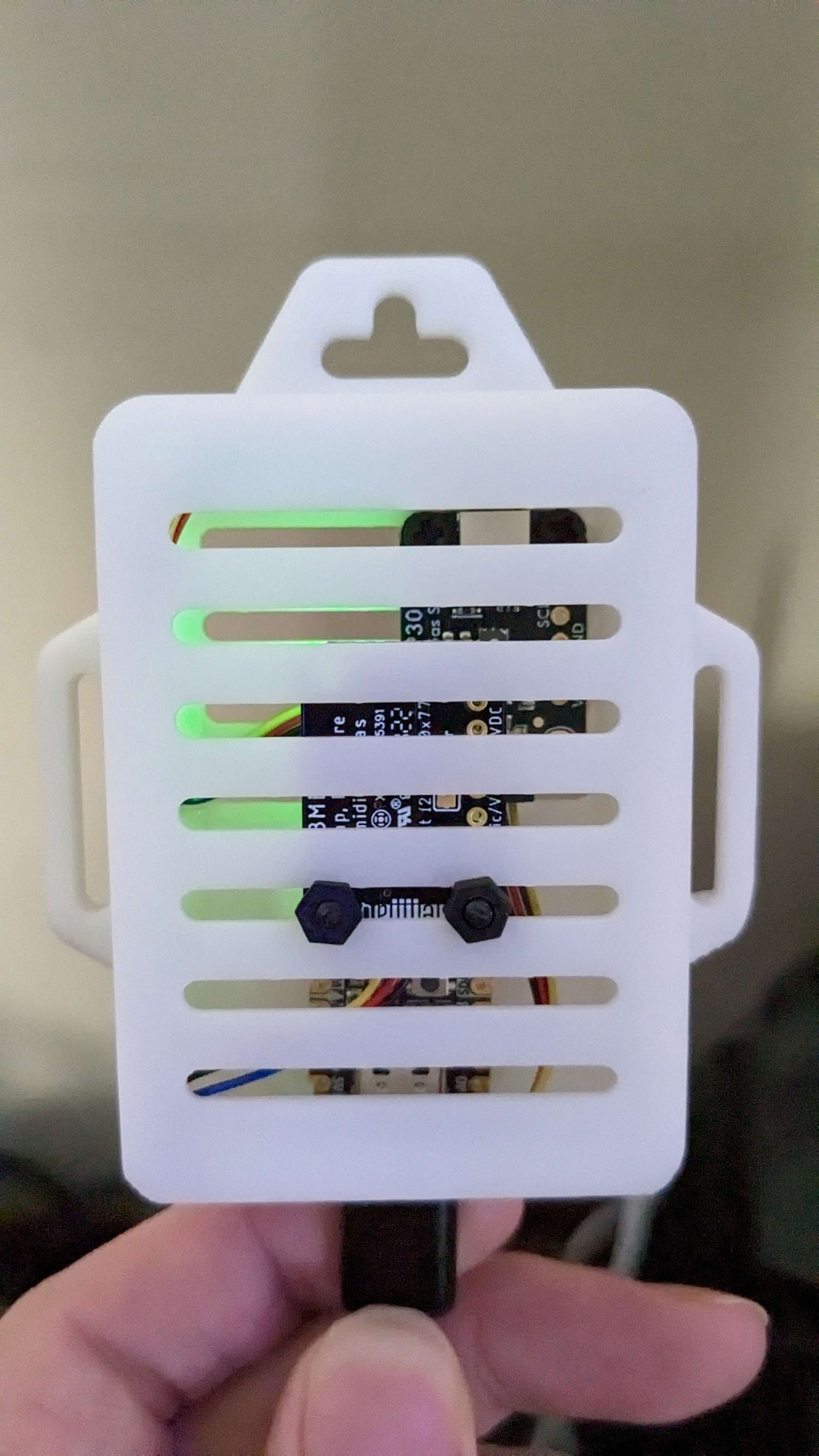
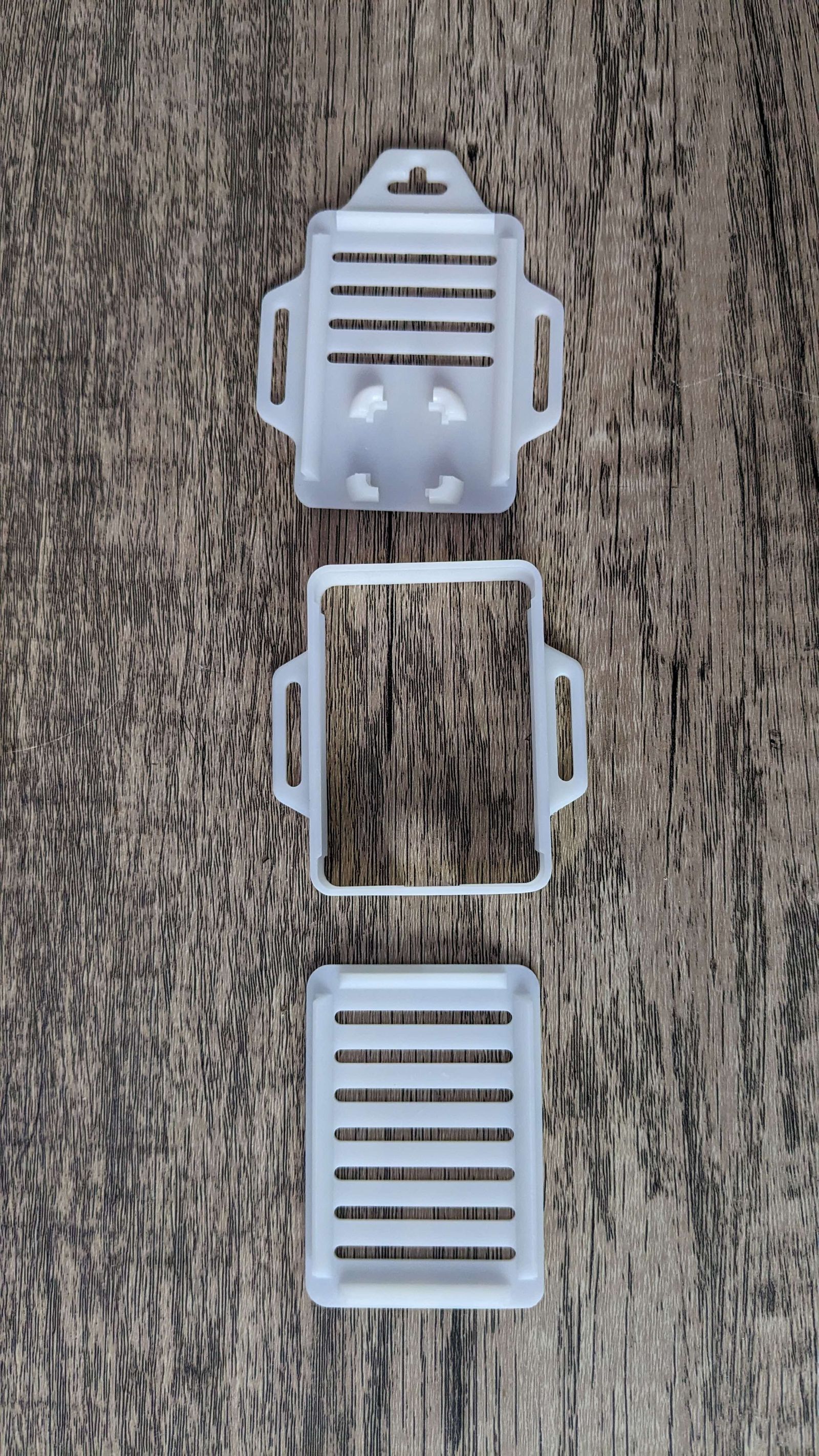
For the device's enclosure, I went with a free 3D print model provided by AdaFruit specifically for the ESP32-S2 QtPy. The case is three parts, all of which simply snap together, providing a snap in holder for the ESP32 that exposes the USB-C port, and mounting grates for sensors, which also serve as vent holes in this design. I had three cases printed by JLC3D in resin for a total cost with shipping of $20.
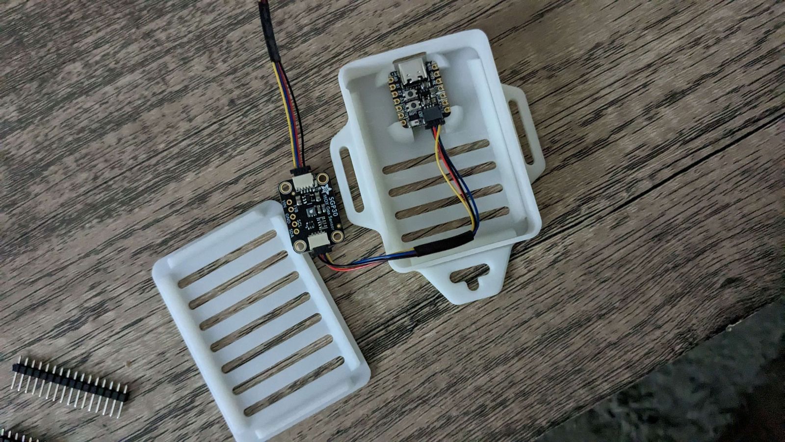
Putting it all together
I highly recommend putting together the device in the enclosure before conducting the calibration process, as the results will often be too skewed to be accurate once placed inside the enclosure. The build process is very simple and took all of a minute. Simply snap the ESP32 into the SD card shaped holder on the bottom piece, with the USB-C port pointing towards the hole. Screw in the SGP30 to the bottom vents, attach a STEMMA QT cable between the sensor and ESP32, then snap the bottom to the second layer. Finally, screw the BME680 sensor against the top plate, connect a cable from it to the SGP30, then snap the cover on, making sure to push the cables aside of the bottom sensor.
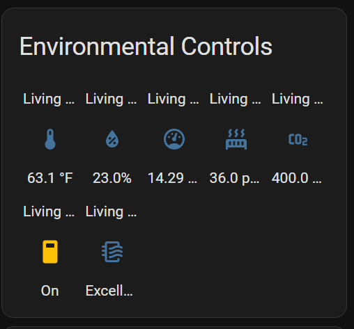
After flashing the ESPHome firmware we customized (The method for this varies depending on the version of ESPHome used, but in the case of the HA addon, I held the boot button on the ESP32 while connecting the USB-C cable to the HA server, putting the ESP32 in download mode. The plugin can then upload the firmware locally.), a number of new sensors will be exposed to Home Assistant:
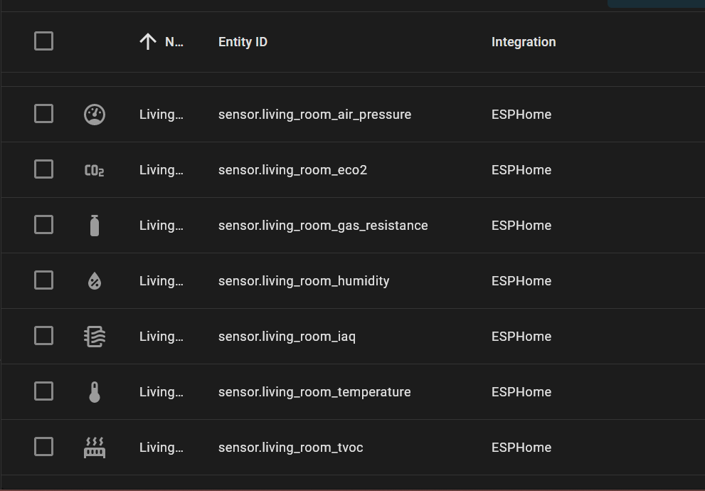
Which can be used to create a card of your room's air quality:
Calibration and storing the calibration values between OTAs.
Once calibration has completed for the SGP30, you will see a line similar to the following in your ESPHome logs: Current eCO2 baseline: 0x86C5, TVOC baseline: 0x8B38. Once you have these values, they can be added to your YAML to persist calibration between OTA updates. To do so, add the following lines, with your own values:
sensor:
  - platform: sgp30
    # ...
    baseline:
      eco2_baseline: 0x86C5
      tvoc_baseline: 0x8B38
See the ESPHome Docs for more information.